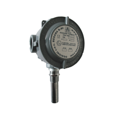
Heat detector TMP2 (4-20mA output)
Operating Instructions
DESCRIPTION:
The TMP2 4-20 heat detectors represent a good solution for the temperature measurement., in industrial environment at very competitive costs. These transmitters are extremely compact, the probe housing is realised in chrome plated brass or in AISI 316 stainless steel. We can also supply an Ex d IIG ATEX version for the use in explosion risk areas.
FEATURES:
TECHNICAL SPECIFICATIONS:
ELECTRICAL SPECIFICATIONS:
ENVIROMENTAL LIMITS:
MECHANICAL SPECIFICATIONS:
ELECTRICAL CONNECTIONS:
First of all note that for the sensor’s connection with the power supply unit, the use of shielded cables is recommended.
Should more than one strand of wire be used in the wiring be sure that the cable screen is continuous and that the conductors are soldered at the joints.
Furthermore it must be remembered that the protective shielding must be earthed only on the side of the control unit or power supply, and must never be connected to the detector.
The use of terminal leads is recommended, otherwise the joints on the power cable must be clamped with flat tab connectors or soldered.
It is best to avoid connection to the same power source used for the detectors, inductive loads could generate ‘noises’ on the power supply to the system.
In any case the use of auxiliary winding on the main power transformer is recommended for supply suppression devices, actuators, sounders or other devices.
The cable screen must be connected to safety earth in safe area.
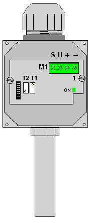
M1 cable assignement :
- Pin 1 - Common
- Pin 2 + 12÷24 Vdc
- Pin 3 U proportional output 4-20 mA
- Pin 4 Shield
 INSTALLATION and MAINTENANCE
Installation and maintenance must be carried out by suitably skilled and competent personnel only. The sensor is calibrated in the factory specifically for the temperature levels requested by the client.
It is good practice to check the response of the sensor every six months, using a mercury thermometer as a reference meter.
You have to introduce the thermometer and the temperature probe into a bath of water at ambient temperature, then wait for 30 minutes until the read values are stabilized. After this, verify that the measured temperature is within the correct parameters.
Otherwise, adjust the trimmer T1 until the output current value (in mA) corresponds to the correct temperature reading (± 1° C).
Before starting any verification procedures all personnel responsible for security should be informed and all alarm systems which might be connected to the system should be switched off.
REQUIRED EQUIPMENT